Course Description
In this course, you will learn about different power systems used all around us, from gear systems in vehicles, to small gas engines, to home electrical work. This course will have you finding solutions to challenges you are given for each unit and problem solving should you run into some trouble. This class will require the use of critical thinking skills, the willingness to learn new information, being able to work with your hands, and your head.
Table of Contents
1. Lab Safety
2. Intro to Energy and Power
3. Mechanical Advantage Unit
-Drag Car
-Slow Car
-King of the Hill
4. Alternative Energy Vehicle
5. Small Gas Engine
6. Home Electricity and AC Power
2. Intro to Energy and Power
3. Mechanical Advantage Unit
-Drag Car
-Slow Car
-King of the Hill
4. Alternative Energy Vehicle
5. Small Gas Engine
6. Home Electricity and AC Power
Lab Safety
Before we started any work in this class, it was very important to go over basic safety to keep us working the best we can. We went over the safety of the tools we would be using in this class. To show our understanding, we were tasked with creating a slideshow about safety in the lab.
Intro to Energy and Power
For this unit, we had to learn about the different types of energy, which is mechanical, chemical, electric, nuclear, thermal, and light. We would need this information for our future projects, such as the alternative energy vehicle, which is talked about later on this page. Energy is defined as the ability to do work. We would need this basic knowledge for the rest of the course.
Mechanical Advantage Unit - Drag Car Project
For this challenge, we were tasked to build a car out of Lego bricks that was as fast as we could make it. It had to make it down the track without any outside assistance. We first learned the difference between speed and torque. Using this, we were able to determine gear ratios that were best suited for the job. While designing our car, we ran into a few problems. Some of our designs, while having speed, lacked torque needed to get the car moving. We had already established a design using a 3:5 ratio we knew we could use in case we didn't find any other ratios that worked, but we eventually found a better balance of torque and speed with a ratio of 1:3. In the end, the fastest time our car had going down the track was 2.15 seconds. In conclusion, being able to actually demonstrate and show how our knowledge applied was useful in understanding how the different ratios work and how they are different in practice and on paper. This helped me to better grasp how the gears worked together so that I could better improve my part of the work on the next project.
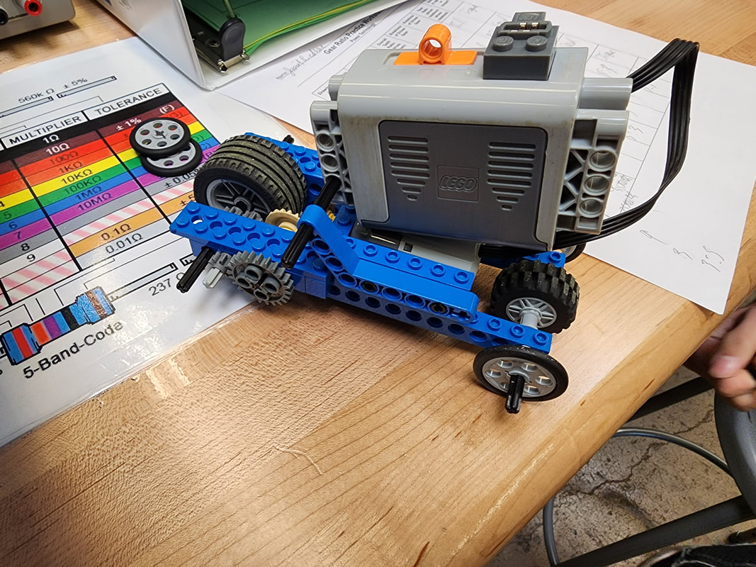
A picture of the car used for the speed competition.
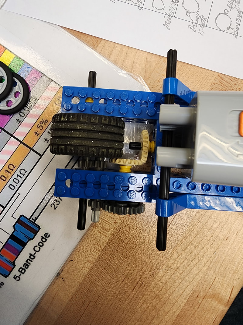
A picture of the gearbox for the car.
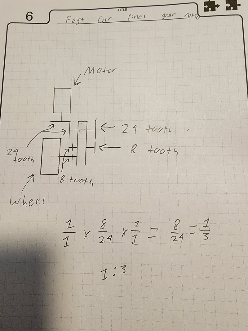
Sketch and calculations for gear ratio.
Slow Car Challenge
What: In this challenge, we were tasked to build a car out of Lego bricks that would go across a 3 inch distance in the longest amount of time possible. The car had to make it across the distance with no outside help. For this project, we a limitation of only being allowed to use one worm gear.
How: Our first step was to build a 200:1 ratio. We had previously created one for another small assignment. Going off this, I made another gearbox with an 81:1 ratio. To work these 2 separate gearboxes together, we had connected them on the side, leaving one sitting further ahead than the other. After attaching the wheels to it and conducting some testing, we had it working, but weren't quite satisfied with it yet. Drawing some inspiration from our research, we had decided to add intermittent power in the form of a crank. We had put this crank all the way at the end of our gear setup. We did this to gain maximum power from this and to make sure the crank was effective at slowing it down. When it came time to test it for our grade, it had surpassed our expectations. We had crossed the 3 inch distance in a time of 2 hours and 49 minutes. There was one problem that we had failed to notice before our official test, however. The shaft the crank utilized was too long and dragged on the ground partially. Despite this problem, our car was still able to cross the finish line. The only effect this problem had was slightly moving the car backwards, but not enough to make it lose ground.
Why: We had known about our 200:1 ratio from a worksheet we were assigned to. We had decided to use as many of our gears as we could with it still making it slower. We had drawn inspiration for our intermittent power from our own research and from what other teams told us.
Other: This project was helpful for me to understand how to use the gears for torque, rather than speed, which will help me in future projects. I know for the next project, King of The Hill, that I will be able to combine the 2 concepts for what the project will require.


Top left: Top view of the car. Crank is shown by the front wheel with the red shaft.
Top middle: First view of 200:1 ratio.
Top right: Second view of 200:1 ratio.
Bottom left: View of 81:1 ratio.
Top middle: First view of 200:1 ratio.
Top right: Second view of 200:1 ratio.
Bottom left: View of 81:1 ratio.
King of the Hill
What: We were tasked to build a car out of Lego bricks that would go up the highest incline possible, while going as fast as possible. We had 3 different levels of incline we could work towards. For this challenge, we were not allowed to use winches.
How: Our first thoughts were how we wanted to get up the steepest track. We began conducting some research based off of what we were told. Some of the most important things we heard was to balance the weight and put most of it in front of a driving wheel. We first came up with a design that relied on the weight making all wheels touch the track. It was heavily flawed with crooked steering, lack of traction, and bad weight distribution. After this, we had tried an "L" shape. We had gotten this to work partially, but not enough for the steepest track. After trying to make this work, my teammate had an idea to fix our first prototype to make it work. We had reverted back and applied this idea, getting it to work much better, but not good enough. It had 4 wheel drive this time, but still had steering issues and not enough traction. We first fixed the traction by adding rubber bands. While testing the rubber bands, we had noticed an even bigger problem. The wire to the motor could easily get caught in the gearbox and it did. We fixed this by just covering it with flat Lego pieces that spanned the car. When these 2 problems were fixed, I had devised a way to solve the steering issue. I had added a third pair of wheels that were not driving wheels, but only wheels that were there to guide it and keep it straight. In the end, we got it up the steepest track in 28 seconds.
Why: Our original thought was to base our car off of our drag, but with a different ratio. This is where we got our original idea for the 2 wheels on the inside of our first prototype. Once we found out this didn't work, we knew we needed better steering, so we added an extra wheel to each axle to make 2 pairs. This was because we knew we needed a wider set of wheels to keep it straight. When we switched designs, our idea came from the Pittsburgh Incline.
Other: This project was a good way to have us put our knowledge from the past 2 projects into one where we have to find the right balance of speed and torque. I think it was a good idea to limit us from using winches so that we had to be more creative in how we designed our cars.


Top Left: Side view of the car.
Top Middle: Sketch of gear ratio.
Top Right: Bottom view of the car showing guiding wheels and gears.
Bottom Left: Underside of car showing gears.
Bottom Middle: Top view of the car.
Top Middle: Sketch of gear ratio.
Top Right: Bottom view of the car showing guiding wheels and gears.
Bottom Left: Underside of car showing gears.
Bottom Middle: Top view of the car.
Alternative Energy Vehicle Project
What: For this project, we were tasked to design a gearbox and electrical circuit for a car that had the body assembled. We were given the option to use solar power or hydrogen fuel cells to power the circuit. We had to design it to successfully go 10 feet on a flat surface.
How: The first part of the project we decided to work on was the gearbox. We had first worked from the back of the gearbox to the front, towards the motor. This gave us some trouble, however, as we had too much torque in our car from completely filling up the gearbox. We took our gears apart and then worked forward from the motor. As we went along, we tested the car whenever we added a new pair of gears. Our first pair had proven to not give enough torque, but we had solved our first issue of having too much. A second pair performed a slightly better, but still did not have enough to move the car when it was on the ground. Adding a third pair, we were able to get the car to move when set on the ground, meaning we had found the right balance of torque and speed when put under a controlled amount of power. The next part of the project we had to work on was the circuit. Originally experimenting with a parallel circuit, it did not give as much power as desired. Using this information, we decided to connect it in series. This gave us better results that was able to get our car to move without the power supply we had tested it on. The source of power we had mainly decided to use was solar. We had also decided to do a test run with the hydrogen fuel cells as well, which was successful. When we had tested our car against the rest of the class, we had decided to use solar power to get the most out of our vehicle. We had been in 2nd place during this race. Overall for our testing and race, we used rear wheel drive.
Why: This unit was helpful in order to better understand electrical circuits and further our knowledge on gear ratios. Being able to experiment with how the different circuits would yield different results from the same gear ratio, along with different ratios using the same circuit, was able to help show the benefits and drawbacks of different methods of wiring and ratios combined was useful to learn more about both of these subjects.
Other: Although this project was more difficult than the last 3, I think it was helpful to use our knowledge from our previous 3 projects, along with the newer knowledge of circuits to make this project a good challenge that furthered what we knew.


Top Left: The setup of the car we used for the final race
Top Middle: Final gearbox of the car
Top Right: Electrical schematic used for the car
Bottom: Gear ratio sketch and calculations
Top Middle: Final gearbox of the car
Top Right: Electrical schematic used for the car
Bottom: Gear ratio sketch and calculations
Small Gas Engine
What: In this unit, we were tasked with learning about the different systems in a small gas engine, the different strokes of the piston, the parts of the engine, and their functions. Once we had this knowledge, our goal was to complete pre-disassembly tests, and then disassemble the whole engine. Once we had finished this, we took measurements to make sure the engine was in good condition, reassembled it, and run the same tests from the beginning.
Before Disassembling
Before taking apart the engine, we had to run a few tests. The first was a spark test to make sure our spark plug functioned properly. We had success with this test. The next test required us to put oil in the engine. After we had filled it with oil, we did a compression test to make sure that the engine had enough pressure to run properly. Our test showed our engine had a pressure of 75 PSI. After completing these tests, our last step before disassembly was to run the engine. Our first attempt at starting did not work out, most likely due to accidentally flooding the carburetor. When we had tried again the next day, it took a few attempts, but we got our engine running.
Disassembly
Fuel System
Our first goal after testing was to disassemble the fuel system. The first step towards this goal was removing the air filter and the fuel tank. From there, we removed the intake manifold and the valve pressure relief tube. Our final step in this was to remover the muffler.

Removed fuel system.
Ignition System
Our next step was to remove most of the ignition system. We removed the spark plug and moved on to the magneto. We had to be careful with this step so we did not ruin the bolts holding it down. We successfully removed the magneto, along with the air vane governor.


Left: The removed ignition system, along with the recoil starter.
Right: The engine with the fuel system and ignition system removed.
Right: The engine with the fuel system and ignition system removed.
Starting Clutch and Flywheel
Our next task was to remove the starting clutch and the flywheel. This step gave us some trouble, as it seemed that the group who had worked on this engine previously, had torqued the starting clutch down too much. After getting it unstuck, we removed the flywheel with no more problems.

Starting clutch and flywheel removed.
Cylinder Head and Valves
Next, we worked on the cylinder and the valves. We first needed to remove the cylinder head so that the valves could slide out. Once we had done this, we were able to see the piston head, the intake valve, and the exhaust valve. We had then taken the valve cover off so we could access the retaining clips and remove both valves.We started with the intake valve, after which, we removed the exhaust valve.


Top Left: Cylinder head removed.
Top Right: Valve cover removed.
Bottom Left: Valves removed, shown from the front view.
Bottom Right: Valves removed, shown from a side view. Tappets visible.
Top Right: Valve cover removed.
Bottom Left: Valves removed, shown from the front view.
Bottom Right: Valves removed, shown from a side view. Tappets visible.
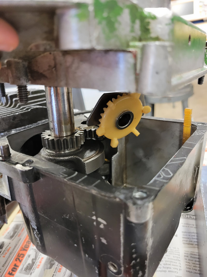
Crankcase
The next step for us was to take apart the crankcase. We took the crankcase cover off and removed its gasket. From here, we removed the oil slinger from the lubrication system. After this, we were able to remove the camshaft easily and remove the tappets. We then had to remove the piston connecting rod from the crankshaft and then remove the piston from the cylinder. Once, we had removed these parts, we removed the crankshaft, removing the mechanical system and completing the disassembly process.


Top Left: Crankcase opened up.
Top Middle: Oil slinger removed
Top Right: Camshaft removed, tappets visible.
Bottom Left: Crankshaft and piston removed.
Bottom Middle: Crankshaft out of the engine.
Bottom Right: Piston out of the engine.
Top Middle: Oil slinger removed
Top Right: Camshaft removed, tappets visible.
Bottom Left: Crankshaft and piston removed.
Bottom Middle: Crankshaft out of the engine.
Bottom Right: Piston out of the engine.
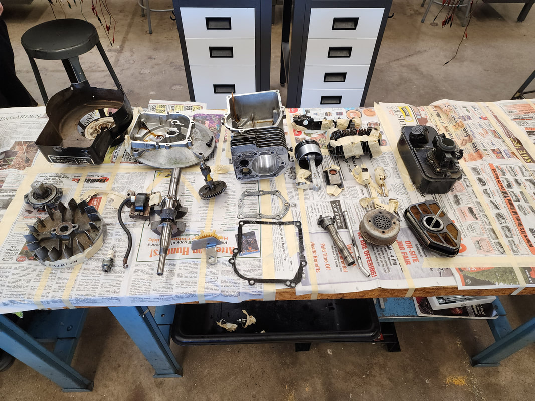
All the parts from the disassembled engine.
Measurements
Once we had disassembled the engine, we had to take measurements to make sure parts of the engine were in spec. We first measured the inside of the cylinder to make sure it had not worn out. We had to use this to find out what the taper was in the cylinder. Then, we had to then measure the valve clearances. We then had to measure the camshaft to make sure that it had not been worn out from working the tappets. Finally, we measured the crankshaft to make sure it had not worn out from moving the piston. All of the areas we had to measure were in spec on our engine.
Reassembly
For reassembly, we had to learn how to use a new tool: the torque wrench. This was crucial to putting the parts back together so that they would stay together while the engine was running. We had a manual for the engine that told us the amount of torque needed for each part that needed it. We had to make sure to understand the difference between inch pounds and foot pounds, as different parts required these different units.
Cylinder and Crankcase
Our first step on reassembly was to get the cylinder and crankcase put back together. We first put the piston back in and positioned it so that we could reattach it to the crankshaft, which was our next step. Once we had reattached the 2, we had to put the tappets back in, followed by the camshaft. When we put the camshaft back in, we had to line up markings on the gear of the crankshaft with markings on the camshaft gear. This was to make sure the valves were timed properly. Once we had the camshaft in place, we put the oil slinger back on. This concluded work on the inside of the crankcase. When we went to put the crankcase cover back on and torqued down, we noticed a stripped bolt. We determined it would not cause any problems for our purposes.


Left: In the process of using the torque wrench on the connecting rod.
Middle: Reassembled connecting rod. Tappets visible
Right: Crankcase put back together with camshaft and oil slinger.
Middle: Reassembled connecting rod. Tappets visible
Right: Crankcase put back together with camshaft and oil slinger.
Valves and Cylinder Head
The next step was putting the valves back together. This was achieved in the reverse way of taking them out. We pushed the retaining clips in instead of pulling them outward. Once we had the valves back in place, we could reattach the cylinder head with the inch pound torque ratchet. Once this was done, we reattached the muffler, intake manifold, and valve pressure relief tube for ease of access. Before reattaching the intake manifold, we had replaced its gasket, as it had been ripped before we took it off.

Intake and exhaust valves put back into the engine. Intake valve open showing the engine would be on the intake stroke.
Flywheel, Starting Clutch, and Magneto
Next up, we had to reattach the flywheel, starting clutch, and properly space the magneto. To reattach the flywheel, we had to slide it onto the crankshaft and put the flywheel key in along with it. We then had to thread the clutch onto the crankshaft so we could torque it down. For the clutch, we had to use the torque ratchet designed for foot pounds. We used the same process for putting it on as we did taking it off, but in reverse. Once we had the flywheel and clutch reattached, we had to space the magneto the right distance from the flywheel. We used 2 index cards on top of each other to achieve the right space. It took a few tries to get it properly attached, but we had gotten it in place with the right distance. Another part attached to the magneto was the air vane governor, which used one of the same bolts the magneto did, so they were attached at the same time.

Flywheel, starting clutch, magneto, and air vane governor reattached.
Final Steps
Our next move was to reattach the fuel tank. While attaching this, we had noticed one of the 2 bolts was stripped. While this is a problem, we did not worry about it because it would only undergo light testing that wouldn't bring about any problems. Our last step in the reassembly process for now was we had put the recoil starter back onto the starting clutch. There was another bolt stripped on this, but as with the previous bolts, we determined it was not a problem for our purposes.


Top Left: Inside the flywheel housing.
Top Right: Side view of the engine showing muffler and reattached flywheel housing.
Bottom Left: Engine mostly reassembled without the air filter on top of the carburetor. Spark plug attached for documentation purposes.
Bottom Right: Fuel tank attached to engine.
Top Right: Side view of the engine showing muffler and reattached flywheel housing.
Bottom Left: Engine mostly reassembled without the air filter on top of the carburetor. Spark plug attached for documentation purposes.
Bottom Right: Fuel tank attached to engine.
Final Testing
Now that our engine was reassembled, we had to run the same tests as we did before disassembly. We ran a spark test, and got a good spark. Our compression test yielded better results than our first. Instead of 75 PSI, we had 80 PSI. When we went to start our engine, it started up much faster and easier than it had the first time testing. This was in part due to the flywheel not being over torqued, as it likely was before disassembly.
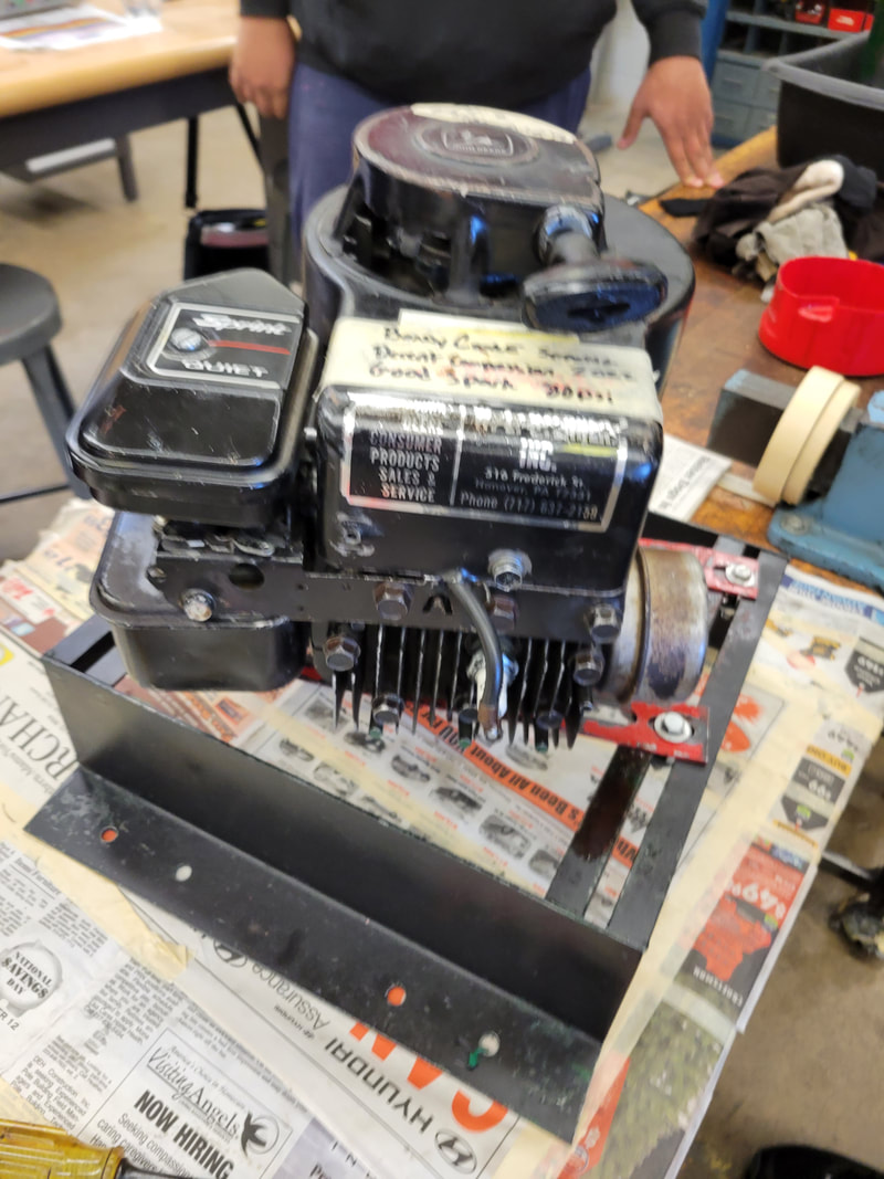
Engine entirely reassembled.
Final Thoughts
Why this was important: I think this project was one that was very important. It brought with it learning how to use tools that mechanics would need to know how to use. As previously stated, we had to learn about the 4 strokes, what the parts were, and how they worked together to achieve the goal of running the engine. This was very helpful to better understand the reasoning behind what we were doing in the disassembly and reassembly. Without knowing these functions and parts, the project wouldn't have made as much sense or provided for very much learning.
Other: While this project was very different from the previous projects, this one was very enjoyable and informative. I enjoyed being able to learn how to use the tools, the terminology, how the parts worked, and the process used for repairing engines.
Other: While this project was very different from the previous projects, this one was very enjoyable and informative. I enjoyed being able to learn how to use the tools, the terminology, how the parts worked, and the process used for repairing engines.
Home Electricity and AC Power
What: In this unit, we had to learn about AC power and how buildings are wired. We had to apply this knowledge by making 8 separate circuits, each with a different function. We tested the circuits by checking continuity, then plugging them into an outlet to see if we had correctly assembled the circuit. Before we began our work, we had to create an extension cord to plug into the outlet for testing. We had to learn about the hot, neutral, and ground wires, along with the application of them and where they were needed. We learned about the different types of cable used in buildings and the tools electricians use.
Circuits
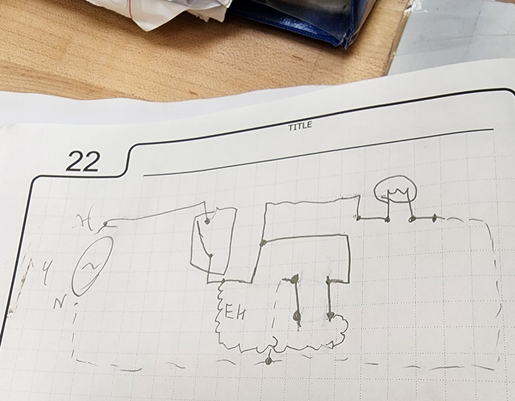
Circuit 1
For our first circuit, we had the task of wiring an on/off switch to a light bulb. We connected the cord to the bottom so we could test it with electricity. We then wired the lamp base to the top of the switch so we could activate and deactivate it. the hot wire was the only wire hooked to the switch.


Top Left: Schematic of the circuit.
Top Right: Circuit in action.
Bottom Left: Wiring of the lamp.
Bottom Right: Wiring of the switch.
Top Right: Circuit in action.
Bottom Left: Wiring of the lamp.
Bottom Right: Wiring of the switch.
Circuit 2
For circuit 2, we had to make the bottom half of an outlet hot at all times. We connected it to the bottom half of the circuit in the box with the switch. The lamp's wiring stayed the same.


Left: Wiring of the switch.
Middle: Circuit in action.
Right: Wiring of the receptacle.
Middle: Circuit in action.
Right: Wiring of the receptacle.
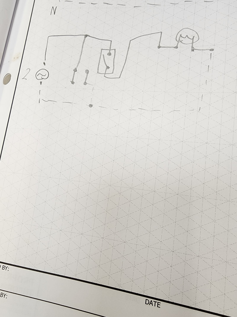
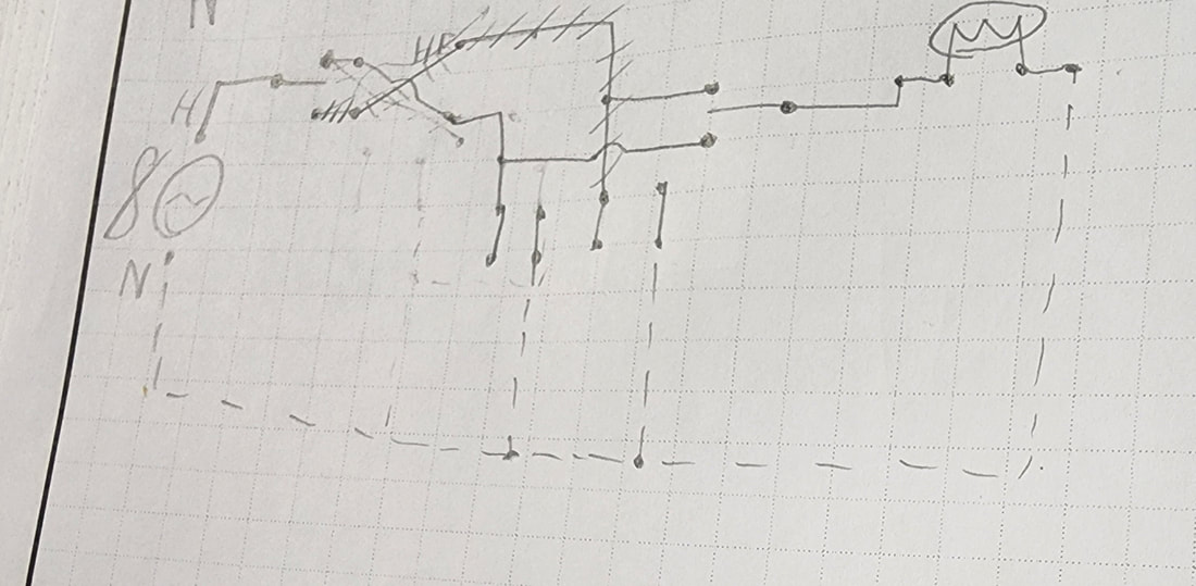
Schematic
Circuit 3
For circuit 3, we had to use the same setup, but make it so the top half of the receptacle was operated off of the same switch operating the light. We were given the challenge to only use 3 pieces of cable, so for this circuit, instead of using 14-2 cable, we had to use 14-3 for the second hot wire.


Top Left: Circuit in action.
Top Middle: Receptacle wiring.
Top Right: Switch flipped, showing the outlet is activated.
Bottom Left: Bottom outlet always hot.
Bottom Middle: Switch wiring.
Top Middle: Receptacle wiring.
Top Right: Switch flipped, showing the outlet is activated.
Bottom Left: Bottom outlet always hot.
Bottom Middle: Switch wiring.
Schematic
Circuit 4
Our next task was to create a system that operated 2 lights in parallel off of one switch. We had to rewire our section slightly to achieve this.


Left: Circuit in action.
Middle: Left bulb slightly unscrewed to show the other bulb works without it.
Right: Wiring of the lamp shown on the left in the picture of the circuit.
Middle: Left bulb slightly unscrewed to show the other bulb works without it.
Right: Wiring of the lamp shown on the left in the picture of the circuit.
Schematic
Circuit 5
For circuit 5, we had to change circuit 4 slightly to make it so it ran 2 lights in series, while working off a single switch. This circuit would normally break code, as it is inefficient and there are much better ways to wire lights. When in series, if one light went out, all of the lights would go out along with it. Another reason we don't want to wire lights like this is because as we add more lights, the power to each decreases with each bulb.


Left: Circuit in action. Note the bulbs are both dimmer from series wiring.
Middle: Bulb on the left is slightly unscrewed to demonstrate that it requires all the bulbs to work for the circuit to function.
Right: Wiring of a lamp.
Middle: Bulb on the left is slightly unscrewed to demonstrate that it requires all the bulbs to work for the circuit to function.
Right: Wiring of a lamp.
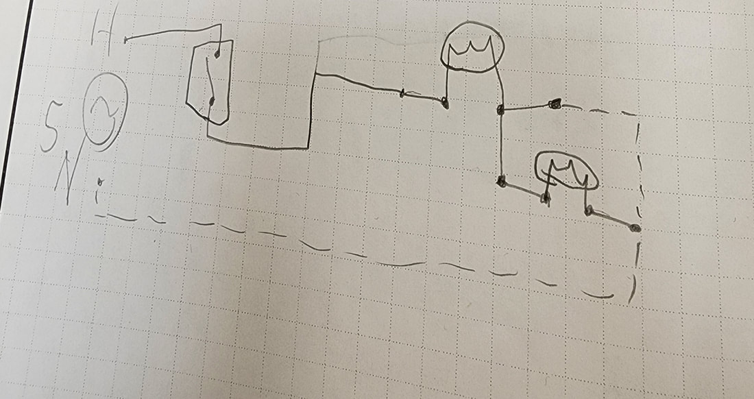
Schematic
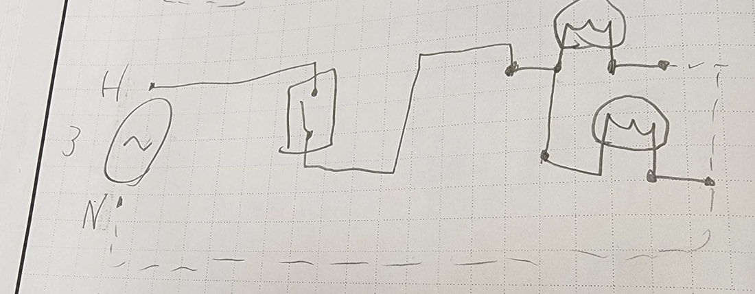
Circuit 6
Circuit 6 required us to operate a lamp from 2 different switches that operated independently. We had to rework most of our circuit to achieve this. We were required to use more 14-3 cable for the second hot wire to hook to the second 3 way switch.


Left: Circuit in action.
Middle: Wiring of the first switch.
Right: Wiring of the second switch.
Middle: Wiring of the first switch.
Right: Wiring of the second switch.
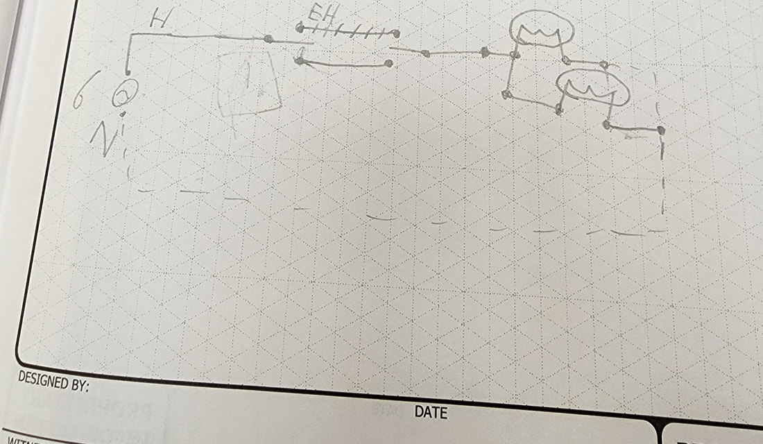
Schematic
Circuit 7
For circuit 7, we had to make it so we could operate a lamp from 3 different areas, this time adding a four way switch.


Top Left: Circuit in action.
Top Right: Wiring of first switch.
Bottom Left: Wiring of second switch.
Bottom Right: Wiring of third switch.
Top Right: Wiring of first switch.
Bottom Left: Wiring of second switch.
Bottom Right: Wiring of third switch.
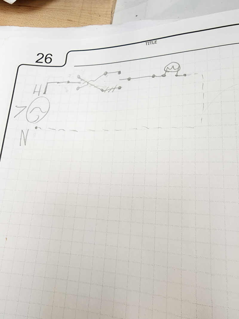
Schematic
Circuit 8
Circuit 8, the final one, we had to come up with our own design to create. We decided to modify our circuit to operate 1 lamp from 2 switches, while having the first switch alternate between making 1 of 2 receptacles hot. We kept the final switch the same as the previous circuit. While this does not have much purpose, we got it to work as designed.


Left: Circuit in a state where it could operate with power.
Middle: Wiring of first switch.
Right: Wiring of the 2 receptacles.
Middle: Wiring of first switch.
Right: Wiring of the 2 receptacles.
Schematic
Final Thoughts
Why this was important: Home electricity is something that is important to have at least a basic understanding of. Electricity can be very dangerous if worked on by someone who does not understand it. In this class, we covered the basics, while also diving a bit deeper in our learning and understanding. This class was important because it helps to provide a knowledge that we can apply later in life when we are homeowners. Being able to work on your own home safely and effectively can be very helpful, and this project helped us to work towards this.
Other: This project, while related to the alternative energy project earlier in this course, had its differences which provided for a better understanding of electricity overall. I enjoyed this unit because it gave us a chance to learn about the tools an electrician would use and how to apply the skills needed to work with AC power. This class allowed me to consider a career path which I did not consider very much beforehand.
Other: This project, while related to the alternative energy project earlier in this course, had its differences which provided for a better understanding of electricity overall. I enjoyed this unit because it gave us a chance to learn about the tools an electrician would use and how to apply the skills needed to work with AC power. This class allowed me to consider a career path which I did not consider very much beforehand.
Overall Thoughts on the Course
I find that taking Power Tech was a very good use of a class in school. I have learned about how many different things in our everyday lives work that many don't think about too much, such as the electricity in our homes and the engines in our cars. This class has taught me many skills that are very good for helping me understand what is behind the scenes of many things and the moving parts of the machines we use so often. I have learned many different techniques and tools for working on a variety of different things such as engines and AC power systems. I have learned concepts that I previously would not have thought of very much, such as the gear ratios that are needed to move many machines. Taking this class has opened my eyes to many different career options I previously didn't think of as much, such as being an electrician or working on small gas engines. As said earlier, I believe that taking this class was very beneficial to me, and has helped me to see many different aspects of our world in a different light.
